
Electrolux Washing Machine Manual PDF: A Comprehensive Guide
Accessing the Electrolux washing machine manual in PDF format streamlines operation‚ troubleshooting‚ and maintenance‚ offering a readily available resource for all users.
Electrolux washing machines are renowned for their innovative technology‚ efficiency‚ and commitment to fabric care. This introduction provides a foundational understanding of these appliances‚ preparing you to utilize your machine to its fullest potential. From advanced features designed to protect delicate garments to powerful wash programs tackling heavily soiled items‚ Electrolux caters to diverse laundry needs.
Understanding the core functionalities and benefits of your Electrolux washer is crucial for optimal performance and longevity. This manual‚ available as a convenient PDF‚ serves as your comprehensive guide‚ detailing everything from initial setup and daily operation to advanced troubleshooting and maintenance procedures. It ensures a seamless laundry experience‚ maximizing cleaning results while minimizing energy and water consumption.
Why Use a PDF Manual?
Utilizing a PDF version of your Electrolux washing machine manual offers unparalleled convenience and accessibility. Unlike traditional paper manuals‚ a PDF is readily available on any device – smartphones‚ tablets‚ or computers – eliminating the need to search for a physical copy. This digital format allows for quick and easy searching‚ pinpointing specific information regarding features‚ error codes‚ or troubleshooting steps in seconds.
Furthermore‚ PDF manuals are environmentally friendly‚ reducing paper consumption. They are also easily backed up‚ ensuring you always have access to vital information‚ even if the original is misplaced; The downloadable format ensures you have the most up-to-date version‚ reflecting any revisions or updates from Electrolux‚ guaranteeing accurate guidance for your appliance.
Understanding Your Electrolux Washing Machine Model
Proper identification of your Electrolux model‚ utilizing the manual‚ unlocks access to tailored features‚ specifications‚ and optimal performance guidance.
Identifying Your Model Number
Locating your Electrolux washing machine’s model number is crucial for accessing the correct PDF manual and specific support resources. This unique identifier ensures you receive information tailored to your appliance’s features and capabilities. Typically‚ the model number is found on a sticker or plate located on the appliance itself.
Common locations include the inside of the door‚ around the door opening‚ or on the rear of the machine. The manual PDF often references this number for parts diagrams‚ troubleshooting guides‚ and warranty information. Having the model number readily available when contacting customer support will expedite the assistance process. Accurate identification prevents using incorrect instructions‚ potentially damaging your washing machine or voiding its warranty. Refer to your manual’s introductory section for a visual guide to locating the model number on your specific Electrolux model.
Key Features and Specifications
The Electrolux washing machine PDF manual details essential features and specifications‚ empowering users to maximize appliance performance. These specifications encompass capacity (in kilograms or pounds)‚ spin speed (measured in RPM)‚ energy efficiency ratings‚ and available wash programs. Understanding these details allows for optimal laundry handling and cost-effective operation.
Key features highlighted in the manual often include specialized wash cycles like steam cleaning‚ allergen removal‚ or delicate fabric care. The PDF also outlines dimensions‚ water consumption per cycle‚ and power requirements. Familiarizing yourself with these specifications ensures proper installation and prevents overloading‚ extending the lifespan of your machine; Detailed charts and diagrams within the manual provide a comprehensive overview of your model’s capabilities.
Installation and Setup
The Electrolux PDF manual guides users through proper installation‚ covering unpacking‚ hose connections‚ electrical safety‚ and leveling for optimal performance.
Unpacking and Initial Inspection
Before operating your new Electrolux washing machine‚ the PDF manual emphasizes a thorough unpacking and initial inspection process. Carefully remove all packaging materials‚ including shipping bolts and foam supports‚ which are crucial for preventing damage during transit. The manual instructs users to verify the machine’s physical condition‚ checking for any dents‚ scratches‚ or visible defects.
It also details confirming the inclusion of all accessories – hoses‚ drainpipe‚ and the manual itself. Inspect the power cord and plug for any signs of damage. The PDF highlights the importance of retaining the packaging for potential returns or warranty claims. Document any discovered damage with photographs and immediately contact the retailer or Electrolux customer support‚ referencing your model number as detailed in the manual.
Connecting Water Supply and Drain Hose
The Electrolux washing machine PDF manual provides detailed instructions for safely connecting the water supply and drain hose. It stresses using only the supplied hoses and avoiding any kinks or sharp bends‚ which can restrict water flow. The manual specifies connecting the inlet hose to a cold water supply with adequate pressure‚ typically between 10 and 120 PSI.
Regarding the drain hose‚ the manual illustrates proper positioning – ensuring it’s securely inserted into a standpipe or laundry tub‚ at the correct height to prevent siphoning. It cautions against extending the drain hose unnecessarily. Always check for leaks at both connections after installation‚ as highlighted in the PDF‚ and tighten as needed.
Electrical Connection and Safety
The Electrolux washing machine manual PDF emphasizes crucial electrical safety precautions. It mandates that installation be performed by a qualified electrician‚ adhering to local and national electrical codes. The manual details the required voltage and amperage‚ typically 120V/60Hz‚ and stresses the importance of a dedicated‚ grounded circuit.
Never use extension cords or adapters‚ as they pose a fire hazard. The PDF warns against operating the machine with a damaged power cord and instructs users to immediately disconnect the appliance if any electrical issues are detected. It also highlights the importance of ensuring the earth connection is functioning correctly‚ preventing electric shock. Always consult a professional for repairs.
Operating Instructions
The Electrolux manual PDF guides users through loading‚ detergent use‚ and program selection‚ ensuring optimal cleaning performance and garment care with ease.
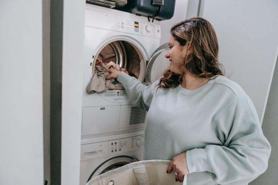
Loading Laundry Correctly
Your Electrolux washing machine’s PDF manual emphasizes proper loading techniques for optimal results. Avoid overloading; consult the manual for specific weight capacities based on your model. Distribute items evenly within the drum to maintain balance and prevent excessive vibration during the wash cycle.
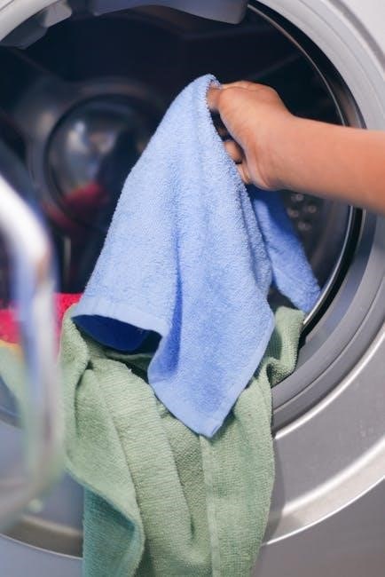
Separate laundry by fabric type‚ color‚ and soil level before loading. Delicate items should be placed in a mesh laundry bag to protect them from damage. Ensure that pockets are empty to prevent damage to the machine or other garments.
Bulky items like blankets or comforters require sufficient space to move freely; avoid cramming them into the drum. Refer to the manual for guidance on washing these larger items effectively. Following these guidelines‚ as detailed in your PDF manual‚ will extend the life of both your clothes and your washing machine;
Detergent Dispenser Guide
The Electrolux washing machine PDF manual provides a detailed guide to utilizing the detergent dispenser correctly. Typically‚ it features separate compartments for pre-wash detergent‚ main wash detergent‚ and fabric softener. Always use the recommended amount of detergent‚ as excessive suds can hinder washing performance and potentially damage the machine.
Powdered detergent should be poured into the designated compartment‚ while liquid detergent can often be added directly into the drum‚ depending on your model – consult the manual. Fabric softener should never be poured directly onto clothes; use the appropriate compartment to ensure even distribution.
Regularly cleaning the detergent dispenser‚ as outlined in the manual‚ prevents buildup and ensures optimal functionality. Incorrect detergent usage can void your warranty‚ so adherence to the PDF guide is crucial.
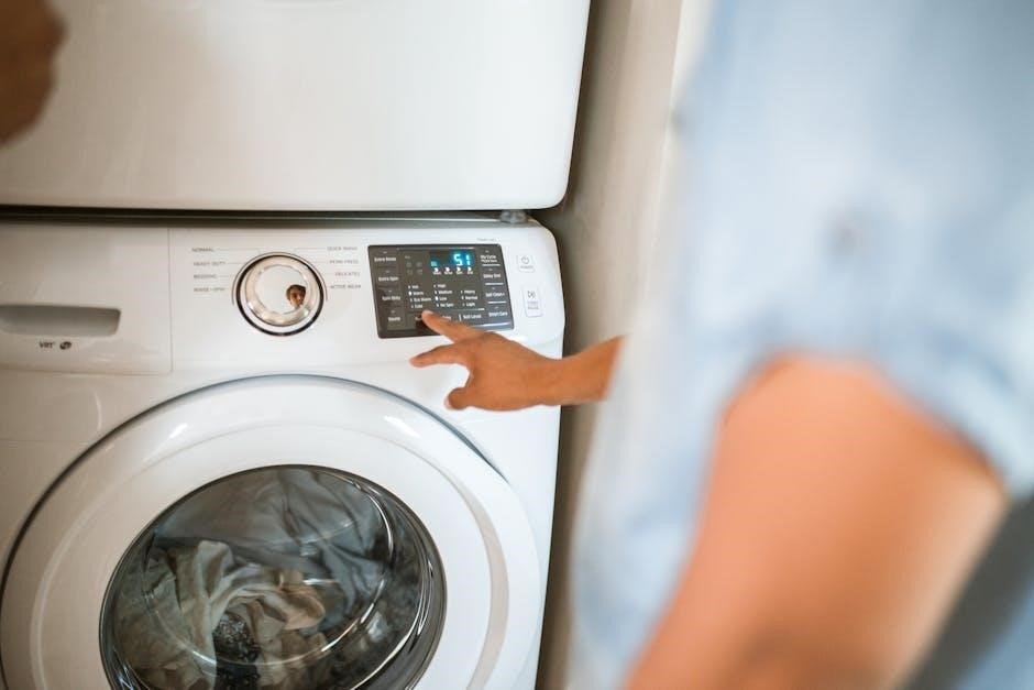
Selecting Wash Programs
Your Electrolux washing machine’s PDF manual details each available wash program‚ ensuring optimal garment care. Programs are categorized by fabric type and soil level – from delicate silks to heavily soiled cottons. The manual explains the temperature‚ spin speed‚ and wash duration for each cycle.
Common programs include Cotton‚ Synthetics‚ Delicates/Silk‚ Wool‚ and Quick Wash. Specialized cycles like Anti-Allergy or Jeans Wash may also be available. Before starting a wash‚ carefully review the garment care label and select the corresponding program.
The manual clarifies any program-specific settings‚ such as pre-wash options or extra rinse cycles. Utilizing the correct program extends the life of your clothes and maximizes washing efficiency‚ as detailed within the PDF.
Wash Programs Explained
The Electrolux manual PDF thoroughly describes each wash program‚ detailing temperature settings‚ spin speeds‚ and ideal fabric types for optimal cleaning results.
Cotton Program Details
The Cotton program‚ as detailed in the Electrolux washing machine manual PDF‚ is designed for durable‚ everyday cotton items. It utilizes a higher wash temperature – typically between 40°C and 90°C – and a more vigorous mechanical action to effectively remove dirt and stains from items like t-shirts‚ bed linen‚ and towels.
The manual clarifies various sub-settings within the Cotton program‚ including options for pre-wash‚ extra rinse‚ and stain removal‚ allowing customization based on soil level. Spin speeds are also adjustable‚ impacting moisture retention;
Users are advised to consult the garment care labels before selecting this program‚ ensuring compatibility with fabric types. The PDF manual emphasizes avoiding overloading the machine‚ as this can compromise cleaning performance and potentially damage the appliance. Proper detergent dosage‚ as outlined in the manual‚ is crucial for optimal results.
Delicates/Silk Program Guide
The Electrolux washing machine manual PDF highlights the Delicates/Silk program as ideal for fragile fabrics requiring gentle care. This program employs a low wash temperature – typically around 30°C or colder – and a reduced spin speed to minimize stress on delicate fibers like silk‚ lace‚ and lingerie.
The manual strongly recommends using a liquid detergent specifically formulated for delicates‚ avoiding powders that may not dissolve completely and could leave residue. A mesh laundry bag is also advised for protecting particularly sensitive items during the wash cycle.
Users should always check garment care labels before using this program. Overloading the machine is strictly discouraged‚ as it can lead to damage. The PDF manual details the importance of selecting the appropriate water level for the load size‚ ensuring thorough rinsing without excessive agitation.
Wool Program Instructions
The Electrolux washing machine manual PDF emphasizes the Wool program’s specialized design for washing wool garments‚ preventing shrinkage and maintaining fabric integrity. This program utilizes extremely gentle mechanical action and cold water – typically below 30°C – to protect wool fibers.
The manual explicitly advises using a detergent specifically formulated for wool or delicate fabrics‚ avoiding those containing enzymes or bleach. It’s crucial to place wool items inside a mesh laundry bag to further minimize friction and potential damage during the wash cycle.
Users are cautioned against using the spin cycle with woolens‚ as it can cause stretching and deformation. The manual recommends removing wool garments immediately after the wash and laying them flat to dry‚ avoiding direct heat or sunlight.
Maintenance and Cleaning
Regular cleaning‚ as detailed in the Electrolux manual PDF‚ ensures optimal performance and longevity of your washing machine‚ preventing odors and buildup.
Cleaning the Detergent Dispenser
The Electrolux washing machine manual PDF emphasizes the importance of a consistently clean detergent dispenser for optimal washing performance. Residue buildup can lead to clogs and reduced detergent effectiveness. To clean‚ typically‚ the dispenser drawer can be removed by pressing a release button or latch – consult your specific model’s manual for precise instructions.
Once removed‚ rinse the dispenser thoroughly under warm running water‚ using a soft brush to dislodge any hardened detergent or fabric softener. Pay particular attention to the compartments and any small nozzles. For stubborn residue‚ a solution of warm water and white vinegar can be used. Ensure all traces of cleaning solution are rinsed away before reinserting the drawer; Regular cleaning‚ ideally monthly‚ prevents issues and maintains the machine’s efficiency.
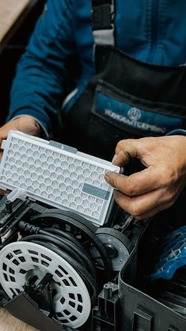
Filter Cleaning Procedures
Your Electrolux washing machine manual PDF details crucial filter cleaning procedures to maintain optimal performance and prevent drainage issues. The filter‚ typically located at the front bottom of the machine behind a small access panel‚ traps lint‚ debris‚ and small objects. Before cleaning‚ always unplug the washing machine for safety.
Place a shallow container and towels to catch any residual water. Carefully unscrew and remove the filter cover‚ then gently pull out the filter. Rinse the filter thoroughly under running water‚ removing all accumulated debris. Inspect the filter housing for any obstructions and clean as needed. Reinstall the filter securely‚ ensuring a watertight seal‚ and close the access panel. Regular filter cleaning‚ every 1-3 months‚ is recommended.
Drum Cleaning Recommendations
The Electrolux washing machine manual PDF emphasizes regular drum cleaning to eliminate detergent residue‚ mildew‚ and unpleasant odors. Over time‚ buildup can affect wash performance and hygiene. A monthly drum cleaning cycle is highly recommended‚ utilizing a washing machine cleaner specifically designed for front-load or top-load machines‚ as appropriate for your model.
Alternatively‚ you can use white vinegar. Pour two cups of white vinegar into the detergent dispenser and run a hot water cycle on the longest setting. After the cycle completes‚ wipe down the drum interior with a clean cloth. Leave the door ajar to allow for ventilation and prevent moisture buildup. Consistent drum cleaning ensures a fresh and efficient washing experience.
Troubleshooting Common Issues
The Electrolux manual PDF provides solutions for frequent problems like non-starting machines‚ drainage issues‚ and deciphering error codes for swift resolution.
Machine Not Starting
If your Electrolux washing machine fails to start‚ the PDF manual guides you through a systematic troubleshooting process. First‚ verify the power cord is securely plugged into a functioning outlet. Consult the manual for specific fuse or circuit breaker requirements for your model.
Next‚ check if the door is properly closed and latched; many models feature a safety lock preventing operation with an open door. The manual details how to address door lock malfunctions. It also instructs you to examine the start/pause button‚ ensuring it’s correctly pressed.
Furthermore‚ the PDF manual explains how to diagnose potential issues with the control panel or internal wiring‚ advising when professional service is necessary. It emphasizes safety precautions before any internal inspection‚ and provides diagrams illustrating component locations.
Water Not Draining
When your Electrolux washing machine retains water after a cycle‚ the PDF manual directs you to first inspect the drain hose for kinks or obstructions. Ensure it isn’t excessively bent or blocked‚ and that it’s positioned at the correct height as specified in the manual.
The manual then guides you through locating and cleaning the drain pump filter – a common culprit for drainage issues. Detailed diagrams illustrate the filter’s location and removal process. It cautions against opening the filter during a cycle and provides instructions for safely draining residual water.
Additionally‚ the PDF manual explains how to check for clogs within the pump itself and advises when to contact a qualified technician if the problem persists‚ potentially indicating a faulty pump or control board.
Error Codes and Their Meanings
The Electrolux washing machine PDF manual dedicates a section to deciphering error codes displayed on the machine’s control panel. These codes are the appliance’s way of communicating specific issues‚ enabling quicker troubleshooting.
The manual provides a comprehensive list‚ detailing each code’s meaning – for example‚ a code indicating a water supply problem‚ a blocked drain‚ or an issue with the door lock. It doesn’t just state the problem‚ but also suggests potential solutions‚ ranging from simple checks like the water tap being open to more complex actions like cleaning the drain pump.
Crucially‚ the manual advises when an error code signifies a need for professional repair‚ preventing users from attempting fixes beyond their expertise and potentially causing further damage.

Safety Information and Warnings
The PDF manual emphasizes crucial safety precautions‚ including electrical grounding‚ child lock usage‚ and emergency procedures‚ ensuring safe operation and preventing accidents.
General Safety Precautions
Before operating your Electrolux washing machine‚ carefully review the safety guidelines detailed within the PDF manual. Always ensure the appliance is properly grounded to prevent electrical shock‚ and never attempt to repair it yourself – contact qualified service personnel for assistance. Keep children and pets away from the machine during operation‚ and never allow them to play with the controls.
Do not wash items that have been cleaned with flammable liquids‚ as this poses a fire hazard. Avoid overloading the machine‚ as this can damage the components and affect performance. Regularly inspect the water supply and drain hoses for any signs of damage or leaks. Disconnect the appliance from the power supply before cleaning or performing maintenance. The manual stresses the importance of responsible usage for longevity and user safety.
Child Lock Feature
The Electrolux washing machine PDF manual highlights the Child Lock feature as a crucial safety mechanism. This function‚ typically activated by a button combination (refer to your specific model’s instructions within the manual)‚ disables the control panel‚ preventing accidental program changes or machine operation by children.
Activating the Child Lock is particularly useful when small children are present‚ ensuring they cannot interfere with a wash cycle or alter settings. The manual details how to both enable and disable this feature‚ often indicated by a specific symbol illuminating on the display panel. It’s a simple yet effective way to enhance household safety and maintain control over the appliance’s functions‚ protecting both the machine and inquisitive little hands.
What to Do in Case of Emergency
Your Electrolux washing machine’s PDF manual provides critical guidance for emergency situations. First‚ immediately disconnect the appliance from the power supply if you observe smoke‚ unusual smells‚ or water leakage. Do not attempt to repair the machine yourself; this could be dangerous.
The manual emphasizes contacting a qualified technician for any repairs. In the event of flooding‚ shut off the water supply to the machine. If someone has come into contact with water and an electrical current‚ do not touch them directly – switch off the power first. Keep the manual readily accessible for quick reference during unforeseen circumstances‚ ensuring a swift and safe response to potential hazards. Prioritize safety above all else.